

HOW TO CUT YOUR FIRST PART WITH CNC
Learning CNC can be a daunting task. Even if you’ve already mastered the concept of moving from napkin sketch to CAD to CAM, you still have to take raw material and cut a part… make some chips, as we say.
Fortunately, making chips doesn’t have to be intimidating. Here at Tormach, we want to make it as simple as possible to start cutting parts. That’s one of the reasons we created our PathPilot control system - because the simplified interface makes it intuitive to start running a real CNC machine. If you haven’t given PathPilot HUB a try, where you can run a no-cost, simulated version of the controller in the cloud, it’s worth a test drive to see just how straight-forward the system can be.
So, how do you cut your first part with CNC? For years, we’ve included a step-by-step tutorial for your first part with a new mill purchase. It’s on page 161 of the operator’s manual. The step-by-step process in the manual is far more extensive, but here’s a rundown, in case you’re still on the fence about getting a machine. This is how you can make your first part with a Tormach mill.
BEFORE YOU START
To keep things simple, through this tutorial, we’ll assume that you don’t have a tool changer. If you do have a tool changer, it’s probably best to do manual tool changes, to help eliminate any unexpected variables.
Here’s a list of the required items and tools you’ll need to make this first part:
- A scrap piece of wood (at least 2 in. × 4 in.)
- 1/8 in. end mill
- 3/8 in. end mill
- Marker
TTS Set Screw Holder: 3/8 in. (PN 31820) - A PCNC 440, 770M, 770MX, 1100M, or 1100MX mill
SETTING UP THE MACHINE AND YOUR WORK
- 1. First, turn your machine on, and get ready to make some chips.
- 2. Verify that the machine can freely move to its reference position. Do this by referencing the Z-axis first by hitting REF Z in the PathPilot interface. Then do the same with the X and Y axes. The REF buttons will have a green indicator when their corresponding axis has been referenced.

- 3. This process establishes a known position for the PathPilot controller. It gives your machine a starting point of reference for the coordinate system. Essentially, it is the baseline in which all of your other CNC instructions will be based.
- 4. Once the axes are referenced, take your woodblock and clamp it into the vise. Make sure that the top is at least 1/4 in. above the top of the vise jaws, to prevent any crashes.
WORK AND TOOL OFFSETS
This part of the process may seem tedious, but it is probably the most important. Making sure your machine knows where your workpiece is located and what the tools you’re using to cut look like is essential to not only make a good part, but also avoid crashing the machine.
SET THE Z ZERO
- 1. If there's already a tool in the spindle, remove it.
- 2. Use a marker to mark the approximate center of the workpiece.
- 3. From the PathPilot interface, in the Tool DRO field, type 0. Then select the Enter key.
- 4. Slowly jog the Z-axis down (-Z) until it's 0.04 in. (1 mm) from the workpiece.
- 5. Put a piece of paper on the workpiece.
- 6. Slowly jog the Z-axis down (-Z), and slowly move the piece of paper back-and-forth.

- 7. Stop jogging the Z-axis when you feel a light pull on the piece of paper, which indicates that it is in contact with the spindle.
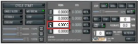
- 8. From the PathPilot interface, in the Z-axis work offset DRO field, type the thickness of the piece of paper. Then select the Enter key.
SET THE X/Y ZEROES
- 1. Put tool 1 (the 3/8-in. end mill) into the spindle.
- 2. Jog the tool so that it's close to the mark you put on the workpiece.
- 3. From the PathPilot interface, select Zero X. Then, select Zero Y.

TOUCH OFF THE TOOL OFFSETS
- 1. Make sure that tool 1 (the 3/8 in. end mill) is in the spindle.
- 2. In the Tool DRO field, type 1. Then, select M6 G43. This tells the machine that you've changed tools, and want to apply the tool length offset.
- 3. Jog the tool so that it's touching the workpiece.
- 4. From the PathPilot interface, on the Offsets tab, type 0 in the Touch DRO field. Then, select Touch Z.
- 5. In the Tool Table window, identify the length entered for tool 1.
- 6. Use a calipers to verify that the length for tool 1 is correct. .
- 7. In the Tool Table window, type the diameter of the tool. Then select the Enter key. Note: Fractions are converted to their decimal equivalents.
- 8. Put tool 2 (the 1/8 in. end mill) into the spindle. y
- 9. Repeat Steps 2 through 7 to measure the tool length for tool 2.
There are a number of different ways to set up your offsets, and every machinist has their own preference. These steps are one of the simpler ways to go about the process. If you want some more details on doing touch-offs, please download the operator’s manual or visit our YouTube channel.
NOW YOU’RE READY TO MAKE SOME CHIPS
There are two different milling operations to create your first part - a pocket and engraving text. To pay homage to our first mill, the PCNC 1100, we’ll use PathPilot’s conversational programming to create a circular pocket and then engrave the letters PCNC.
We’ll be using wood because as a material for milling, it is quite forgiving. While you can still crash your machine when cutting wood, you’re much less likely to run into major challenges with wood than if you were cutting aluminum or steel.
Let’s make your first chips.
CREATE A POCKET
- 1. Our pocket will be 0.100 in. deep (read by machinists as one hundred thou) and 3-1/4 in. in diameter.
- 2. Put tool 1 (the 3/8 in. end mill) into the spindle.

- 3. From the PathPilot interface, in the Tool DRO field, type 1. Then select the Enter key.
- 4. From the Conversational tab, select the Pocket tab.
- 5. On the Pocket tab, select Rect/Circ. PathPilot switches the interface to create a circular pocket.
- 6. Type the following values into the DRO fields, and press Enter on the keyboard after typing each value:
- a. In the Title DRO field, type FIRST PART POCKET.
- b. In the Work Offset DRO field, type G54.
- c. In the Tool DRO field, type.
- d. In the Spindle DRO field, type 5000.
- e. In the Feedrate DRO field, type 60.
- f. In the Z Feedrate DRO field, type 30.
- g. In the Z Clear DRO field, type 0.1000.
- h. In the Pocket Dia. DRO field, type 3.2500.
- i. In the Z Start DRO field, type 0.000.
- j. In the Z End DRO field, type -0.1000.
- k. In the Z DOC DRO field, type 0.1000.
- l. In the Stepover DRO field, type 0.2500.

- 7. From the Conversational tab, select the Drill/Tap tab.
- 8. On the Drill/Tap tab, make sure that the Pattern tab is selected. Then, type the following values into the following DRO fields: a. In the DRO field in the X column of row 1, type 0.0000. Then select the Enter key. b. In the DRO field in the Y column of row 1, type 0.0000. Then select the Enter key.

- 9. From the Conversational tab, select the Pocket tab.
- 10. Select Post to File. PathPilot generates the G-code file, and the Save dialog box displays.

- 11. From the Save dialog box, specify where on the PathPilot controller to save the G-code file.
- 12. Select Save. PathPilot loads the G-code file and opens the Main tab.

RUN THE PROGRAM
- 1. Restrict the speed of the mill so that you can more easily watch the operation running: Set the Maxvel Override slider to 0%.
- 2. Select Cycle Start. The spindle begins to rotate, but the tool won't move, because you restricted the speed in Step 1.
- 3. Change the value of the Maxvel Override slider to speed up, slow down, or stop the mill. When the tool is close to the part, set the Maxvel Override slider to 0%.
- 4. On the Main tab, verify the values in the DRO fields to make sure that they look correct for the current tool position. Then, slowly move the Maxvel Override slider to speed up the mill. For example, if the value in the Z DRO field is 0.2500, the tool should be 1/4 in. above the workpiece.
- 5. After the operation is complete, examine the top surface of the workpiece to make sure that the entire pocket has been cut by the end mill.
ADDING ENGRAVED TEXT
Similar to using conversation for the pocket, we’ll use conversation programming in the PathPilot interface to create engraved text.
- 1. From the PathPilot interface, on the Engrave tab, type the following values into the DRO fields, and press Enter on the keyboard after typing each value:
- a. In the Title DRO field, type FIRST PART POCKET.
- b. In the Work Offset DRO field, type G54.
- c. In the Tool DRO field, type 2.
- d. n the Spindle RPM DRO field, type 5000.
- e. In the Feedrate DRO field, type 60.
- f. In the Z Clear DRO field, type 0.1000.
- g. In the Text DRO field, type PCNC.
- h. In the Height DRO field, type 0.7500.
- i. In the X Base DRO field, type 0.0000.
- j. In the Y Base DRO field, type -0.3750.
- k. In the Z Start DRO field, type -0.1000.
- l. In the Z Depth of Cut DRO field, type 0.0500.

- 1. From the Font list, select FreeMonoOblique.ttf.
- 2. From the Alignment radio buttons, select Center.
- 3. Select Append to File. PathPilot generates the G-code file, and the Append to File dialog box displays.
- 4. From the Append to File dialog box, specify to which file you want to add this operation

- 5. Select Append to File. PathPilot adds the G-code to the file and opens the Main tab.

RUN THE PROGRAM
Because we appended the second operation onto the first, the program starts from the beginning — it re-cuts the pocket. To avoid this in the future, you can post the second operation to a separate file.
- 1. Select Cycle Start. The spindle begins to rotate, and the tool moves to the beginning of the tool path.
- 2. After the operation is complete, put tool 2 (the 1/8 in. end mill) into the spindle.
- 3. From the PathPilot interface, in the Tool DRO field, type 2. Then select the Enter key.
- 4. Restrict the speed of the mill so that you can more easily watch the operation running: Set the Maxvel Override slider to 0%.
- 5. Select Cycle Start. The spindle begins to rotate, and the tool moves to the beginning of the tool path.
- 6. Change the value of the Maxvel Override slider to speed up, slow down, or stop the speed of the mill.
- 7. After the operation is complete, examine the top surface of the workpiece to make sure that the entire phrase has been engraved by the end mill.
And that’s it! You’ve just cut your first CNC chips. With these basic tools, you can create an array of different projects with different tools, but always be sure to measure twice to prevent crashes and when running a program for the first time, be prepared to stop the program if you see a potential crash coming.
Have fun making your first chips!