Just launched my this month’s video with Cutting Tool Engineering for my “CNC Chef” column (a playful reference to the CNCCookbook). In the first video, I covered the subject of tool rubbing. It comes as a surprise to some that if you try to slow down a cut too much, it is actually much worse for tool life. This video discussed chip thinning, a geometric phenomenon that can cause Rubbing if you reduce your Cut Width (also called stepover) too much without increasing feedrates.
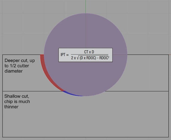
Video is great for learning, but if you prefer something written, I go into considerable detail about rubbing and chip thinning in CNCCookbook’s Free Feeds and Speeds Course. These are geometric effects that simple feeds and speeds calculations based on the classic formulas taught in shop classes don’t account for. They can bite you hard on tool life if you don’t adjust your feeds and speeds to deal with them. In the videos, I describe how to make these adjustments yourself, but I also show how our G-Wizard Feeds and Speeds Calculator will handle them automatically for you. This diagram will help with understanding chip thinning: 
Chip thinning comes into play when you make a cut that’s less than half the diameter of the cutter wide. This is very common, especially with high-speed machining toolpaths. For example, with a 1/2″ end mill, you might specify a cut that’s 20% of the diameter, or 0.100″ wide. The diagram shows a view of a cut looking down along the axis of the endmill from above. Two different cut widths are depicted – one is exactly half the diameter and the other is a lot less. Note the red and blue areas, that depict chips for each. With a cut that is half the diameter or larger, the chip thickness (or chipload) is what you’d expect based on simple feeds and speeds formulas. However, we can see that as the cut goes below half the cutter diameter (blue area), the chip is thinner. That’s chip thinning at work. Specifically, this variety is known as “Radial Chip Thinning.” Now the formula shown will tell you the actual chipload when chip thinning is at work. Your goal is to choose a target chipload, hopefully thick enough to avoid rubbing, and increase your feedrate so that the actual chipload is equal to your target. You’ll be surprised at how much faster you need to go. For example, our 0.100″ cut width requires a feedrate that the simple formulas calculate a chipload of 0.0035″ in order to hit a targeted actual chipload of 0.0028″. That’s a feedrate that’s about 25% faster to get the exact same chipload as we targeted. In some sense, that faster feedrate is “free” since it all goes to getting us back to even. Now imagine a new CNC’er. They've got their new CNC machine and a fistful of shiny new endmills. They're determined not to break a single one as they are just starting out and very cautious. So, they set up an extremely shallow cut width, because that’s conservative, right? Then they dial the feedrate way down on top of that to be even more conservative. Little do they know that all that conservatism has forced the tool to rub instead of cutting, which will overheat it and dull it very quickly. It gets worse–chip thinning can happen in two dimensions when you’re using tools like ball nose end mills and button cutters (indexable tooling with round inserts). It’s worth knowing about these two phenomena, and important to account for them in your feeds and speeds calculations. The good news is that speeding up your feedrates to offset chip thinning not only helps your tool life, it also reduces your cycle time. That’s a twofer well worth having! This post originally appeared in the CNC Cookbook blog.


