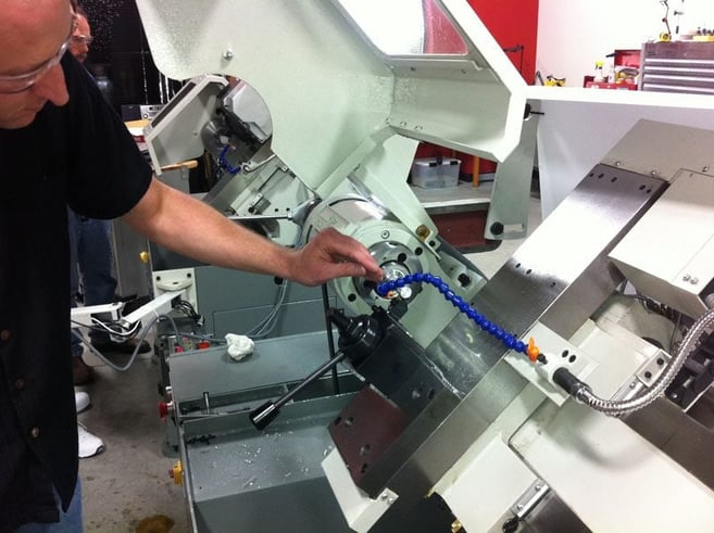
Every machinist knows things work a whole lot better when turning if you can get your tool tip right on the centerline. During a trip to Tormach to test their CNC lathe before I got one years ago, I saw this first hand. I “eyeballed” a tool tip to center and made an OD turning pass. The cut was fine, but the finish seemed poor. So, we set the tool on centerline using the ruler trick:
Put a ruler between the tool tip and the workpiece and crank it down so the ruler is held between the two. If the ruler is not perpendicular to the line from tool tip to center, you need to raise or lower to make it perpendicular. I say “perpendicular” instead of “vertical” because the Tormach is a slant bed lathe.

After doing this, the surface finish changed radically for the better. It’s an easy process that a lot of folks use, but how accurate is it?
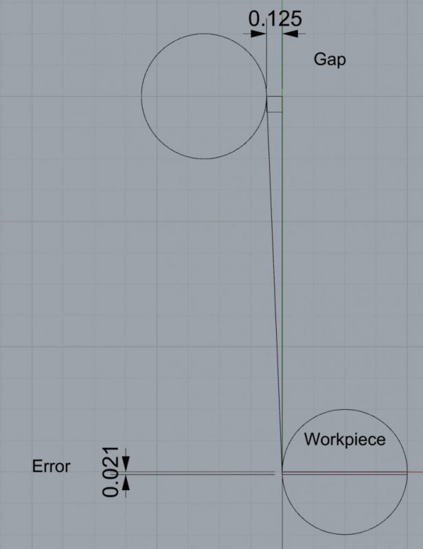
This is a good opportunity to use your CAD program to figure it out. Most CAD programs have a function to draw a line that is tangent to two curves, so I laid out the problem like this:

I drew a 1″ diameter workpiece and put a vertical line tangent to it. Then, I went up that line for 3″, where the top of my 6″ rule would be, and drew a 1/8″ square to represent my Mark I Eyeball’s ability to spot the rule being off. You can probably see an error of less than 1/8″, but probably not 10x less, so this suffices.
Next, I drew another 1″ diameter circle right on that 1/8″ gap. Lastly, I let the CAD program draw a line tangent to the two curves. That line represents the rule cocked at the right angle. Now zoom in to see the endpoint of that ruler line. I put a dimension from that endpoint up to the centerline and got an error of 0.021″.
Easy to calculate the crazy things by sketching them out in CAD (I use Rhino3D and Solidworks for my CAD).
But what about that error? I’m guessing we got down to more like 0.010" or maybe even 0.005″ when we set up the tool. Of course this begs the question, “How close does the tool tip need to be to the centerline when turning?”
How close does the tool tip need to be?
First, let’s understand what’s happening when the tool is above or below centerline. The rake on a lathe tool insert is the angle between the centerline and the angle of the insert’s cutting edge. I’m sure you can already see this coming, but as we move significantly off the centerline, we’re going to change that rake. Eventually, we’ll change it enough that the tool no longer operates as its designers intended, resulting in poor performance of one kind or another–bad tool life, bad surface finish,etc..
But, it gets worse because no tool is infinitely rigid. If the tool is flexing at all, that will change the rake and possibly even the depth of cut as the tip sweeps through the arc of the flex. If the tip is above centerline and is right side up (you can reverse spindle and cut upside down), that flex will cause greater depth of cut.
This is why you want to make sure a parting tool is never above the centerline. Right on it is ideal, but slightly below means any flex or deflection will reduce the depth of cut. Your tool will be forced to “dig in” to the cut, which creates higher deflection forces, more dig-in, and a vicious cycle is started.
Sometimes this results in an oscillation that leads to chatter:
1. Heavy cut deflects the tool down reducing depth of cut.
2. Light forces allow the tool to overcome deflection, so it trends back to the heavier cut.
3. Rinse and repeat.
That’s a recipe for a tuning fork, so deflection has to be managed via rigid tool holders and minimum stick out. But on lathes, also by setting your centerline properly.
Getting back on track, “How close does the tool tip need to be to the centerline when turning?”
Sandvik says you want to be within 0.1mm (0.0039″). This is a decent starting guideline. To achieve it, the end of your 6″ rule must be off no more than 0.023″ instead of 0.125″ from its ideal position. A useful trick is to find a surface you can site the edge on, much as I suggest when using a straight edge to tram vise jaws on the mill. With a slant bed lathe, it may be hard to find a surface at the right angle.
A little reflection about the geometry will tell you that the diameter of the workpiece affects the allowable error in setting the tool tip height. Smaller workpieces need the tip to be more accurately on the centerline. I found one university source that recommends the tool height be set to centerline with an accuracy of 0.005R, where “R” is the radius of the workpiece. So, a 2″ diameter workpiece needs a tool height to centerline difference of no more than 0.005″.
What about micromachining?
The smaller the work you’re doing, the more critical setting centerline height becomes. Getting it right for micromachining can be a real pain.
Setting centerline height is basically setting the “Y” height with a turning tool.
When micro-turning, you will need to be able to set your tool’s Y (height) much more accurately than for conventional turning. Some applications may require the ability to adjust within 1 or 2 tenths. That’s a tight tolerance for this finicky operation!
Plan ahead how you’ll get the tool positioned that accurately relative to your spindle’s centerline.
How do we set the centerline more accurately than with the ruler method?
If you have a height gage and room to use it in your lathe, this is pretty straightforward. Turn a little piece of scrap and measure its diameter with a micrometer. Using the height gage, measure the distance from a reference, such as the tooling plate, to the top of the workpiece. Subtract half the diameter and you now know the distance from the reference to the lathe centerline.
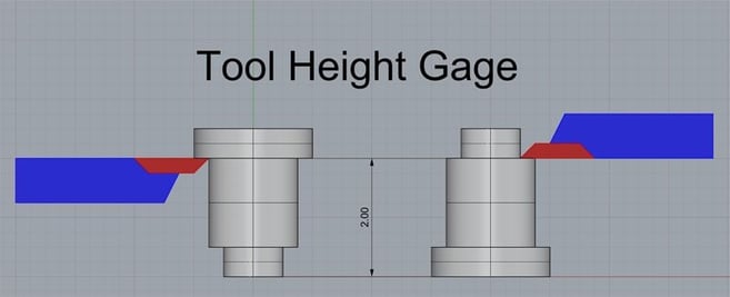
With that information, you can either continue to use the height gage to set heights, or you can make a gage that is exactly that length and is used as a stop to set tool height. An ideal gage has a surface suitable for setting either the top of the insert by coming up against the bottom of the gage surface or the bottom of an upside down insert by coming down onto another gage surface. Something along these lines will suffice:

A well-made tool height gage can be accurate to a few tenths and can be stood on either end to allow setting height from the top of bottom of the insert depending on the orientation in the tool holder. You can even make a couple to experiment with different offsets above, below, and right on the centerline.
This post originally appeared on the CNC Cookbook blog.


